Turbine Stage and Seal Rig
The Turbine Stage and Seal Rig is a unique world leading facility that is continually modified and adapted to study state of the art and next generation turbine aerothermal concepts.
- Turbine Stage and Seal rig (text version)
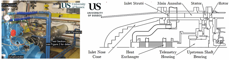
The image on the left shows a photo of the Turbine Stage and Seal rig installed in the TFMRC at the University of Sussex. The image on the right is a cross-sectional drawing that shows the internal construction of the facility.
The Turbine Stage and Seal Rig is a unique world leading facility that is essentially an aerodynamically representative turbine equipped with secondary air system details such as seals and coolant supply configurations. Typically, the details tested include rotor-stator cavity seals, rim seals, stator/rotor shroud seals, radial arm coolant supply arrangement, to name a few.
This test rig was initially commissioned in 2000 and since then has undergone a number of major design changes to adapt to the needs of different research programmes. The turbine has had both single stage and two stage configurations at various stages. For The rig was used to investigate flows in turbine rotor-stator cavity and rim seal regions.
Results and achievements
This facility was successfully utilised for research and testing by OEMs and for EU funded research programmes such as ICAS GT/GT2 and MAGPI.
Further details can be found in the REF2021 impact case study
Technical details
The test section of the rig houses an engine-representative single stage axial turbine, with an overall design pressure ratio of approximately 3:1. The outer radius at the rim is approximately 150 mm and the annulus height is approximately 25 mm and the maximum rotational speed is 14,000 rev/min. The turbine is driven by air at a maximum pressure and temperature of 3.5 bar and 160°C with a mass flow rate of up to 10 kg/s which is supplied to the test section by an adapted (2 MW) Rolls Royce DART aero engine.
Before passing through the turbine, the air passes through a settling chamber and bell mouth to reduce pressure asymmetry and swirl at the inlet to the test section. A hydraulic dynamometer and 3:1 reduction gearbox are used to absorb the power transmitted by the turbine and to decouple the rotational speed and mainstream flow. Cooling and sealing air is supplied to the test section via an Atlas Copco ZT250 oil free compressor with a maximum delivery pressure of 6.5 bar. The temperature of this cooling air can be varied from 20˚C to 170˚C. Both the annulus flow and cooling flow pipelines are insulated.
Temperature of the rotating and stationary surfaces are measured using Type-K thermocouples at various locations. A datatel supplied radio telemetry system provides non-contact transmission of the signals from the rotating thermocouples. Pressures are measured on the non-rotating surfaces in the test rig and recorded using a Scanivalve DSA system.
There is also the capability of measuring gas concentration (i.e., CO2). The running clearances of the stator well geometry are measured using non-contact eddy current sensors. The combination of temperature, pressure and gas concentration measurements are used to detect and quantify the flow ingested into the wheelspace or leakage into the turbine main passage etc.
This is an excellent facility to conduct research and testing on new and advanced air system component designs when component performance and its impact on the turbine stage aerodynamic performance need to be understood simultaneously.
Selected publications
Some notable and recent publications using this test facility include:
- Dixon, J. A., Valencia, A. G., Coren, D. D., Eastwood, D. and Long, C. A. Main Annulus Gas Path Interactions – Turbine Stator Well Heat Transfer , ASME Journal of Turbomachinery. 2013; 136(2)
- Payne, Daniel and Kanjirakkad, Vasudevan (2020) Experimental investigation on the effect of varying purge flow in a newly commissioned single stage turbine test facility. ASME 2020 Turbo Expo, Virtual Conference, 21-25 September 2020. Published in: Proceedings of the ASME Turbo Expo 2020.