Multiple Cavity Rig
The MCR has been a world-leading facility in the study of rotating cavity flows for over two decades and is regularly cited and provides experimental results to run and validate complex numerical simulations.
- Multiple Cavity Rig (text version)
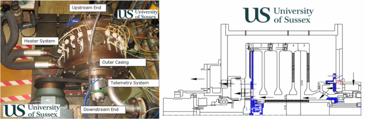
The image on the left shows a photo of the Multiple Cavity Rig installed in the TFMRC at the University of Sussex. The image on the right is a cross-sectional drawing that shows the internal construction of the facility.
The Multiple Cavity Rig (MCR) is designed to investigate flow and heat transfer in the internal air system of a high-pressure compressor under engine-representative operating conditions. This rig was first commissioned in 1996 and since then has undergone several major design iterations and improvements to reflect the shifting needs of the various research programmes it has been part of.
The MCR has been a world-leading facility in the study of rotating cavity flows for over two decades and is regularly cited and provides experimental results to run and validate complex numerical simulations. The main details of the MCR are shown in the figures above.
Results and achievements
Most recently the MCR was used with an aeroengine OEM as part of a programme to develop next-generation prediction capabilities for their thermomechanical design tools.
Further details can be found in the REF2021 impact case study
Technical details
The rotor is constructed from several titanium discs each with an internal outer radius of 220 mm and a bore radius of 70.1 mm. The shaft radius is 52 mm and the axial distance between the discs varies from 46 mm in the cavities to 25.4 mm at the disc bores. Tight clearance aerodynamic seals allow the test section to be pressurised to above atmospheric conditions. In the current configuration the shaft does not rotate. The outer radius of the disc assembly is heated by an array of radiant heaters which can achieve maximum surface temperatures in the region of 220 °C in the test section.
The current modular design allows rapid change between instrumentation packages including optical access used to measure the tangential and axial components of velocity in the cavities a 2D laser doppler anemometer probe, five-hole traversing pneumatic probes and multi-rake rake temperature measurements. The rotor is driven by an electric motor that has a maximum design speed of 8,000 rev/min. Air is supplied to the test rig via an Atlas Copco ZT250 compressor that can deliver up to 0.8 kg/sec at an absolute pressure of 6.5 bar, which is cooled and dried to around 25°C.
Temperatures of both the rotating and stationary surfaces are measured using Type-K thermocouples installed throughout the test rig. A Datatel radio telemetry system provides non-contact data transmission from the 120 rotating thermocouples on the rotor disc pack.
The maximum values of speed, mass flow rate, pressure and surface temperature allow us to test under the following, engine representative, dimensionless operating conditions:
- Rotational Reynolds number = 1.7 x 10⁷
- Axial Reynodls number = 2.3 x 10⁵
- Buoyancy parameter (βΔT) = 0.5
- Rossby number (R) = 0.1
- Grashof number (Gr) = 3.5 x 10¹²
Selected publications
Some notable and recent publications using this test facility include:
- Long, C. A. and Childs, P. R. N (2007) Shroud Heat Transfer Measurements Inside a Heated Multiple Rotating Cavity with Axial Throughflow. International Journal of Heat and Fluid Flow, Vol. 28, pp. 1405-1417.
- Atkins, N. R. (2013). Investigation of a Radial-Inflow Bleed as a Potential for Compressor Clearance Control Paper No. GT2013-95768, Proceedings of ASME Turbo Expo 2013, June 3-7, 2013, San Antonio, USA.
- Alexiou, A., Hills, N. J., Long, C. A., Turner, A. B., Wong, L - S and Millward, J. A. (2000) Discharge Coefficients for Flow Through Holes Normal to a Rotating Shaft. International Journal of Heat and Fluid Flow, Vol. 21, pp. 701-709.
- Fazeli, S. M., Kanjirakkad, V., and Long, C. (March 31, 2021). "Experimental and Computational Investigation of Flow Structure in Buoyancy-Dominated Rotating Cavities." ASME. J. Eng. Gas Turbines Power. July 2021; 143(7): 071026.
- Puttock-Brown, M. R., and Long, C. A. (March 15, 2021). “Heat Transfer Analysis in a Rotating Cavity With Axial Through-Flow.” ASME. J. Eng. Gas Turbines Power. May 2021; 143(5): 051026.