Bolt Windage Rig
The Bolt Windage rig is ideally suited for studying rotor-stator cavity aerodynamics and heat transfer involving real geometry features such as seals and protrusions. The size and rotating speed of the discs allows for tests to be conducted close to real engine surface velocity conditions.
- Bolt Windage Rig (text version)
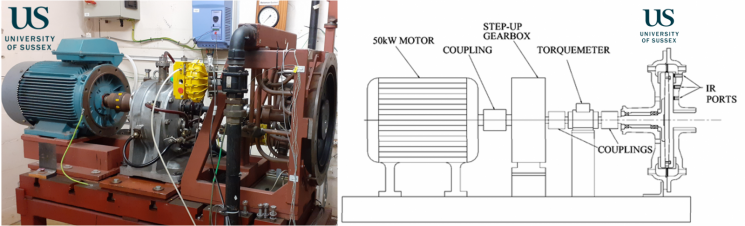
The image on the left shows a photo of the Bolt Windage Rig installed in the TFMRC at the University of Sussex. The image on the right is a cross-sectional drawing that shows the internal construction of the facility.
The Bolt Windage rig is essentially a rotor-stator cavity rig with a single disc rotating inside a casing. The name came about as it was first used for studying and correlating windage losses from bolts and protrusions that are attached to the rotating disc surfaces. The figure above shows a photograph of the rig and a general assembly of the rig.
Results and achievements
This facility was successfully utilised for research and testing by OEMs and for EU funded research programmes such as ICAS GT2 and GROWTH.
Technical details
In its current build, the rig consists of a shaft mounted titanium alloy disc with an outer radius of 225 mm enclosed within a sealed steel pressure casing. The gap ratio, G, is 0.1. Around the outer rim of the disc there is a labyrinth seal and a stator mounted shroud encases the cavities on either side of the disc. The disc is driven by a 50 kW motor through a 5:1 step up gearbox. An in-line torquemeter is mounted between the gearbox and the disc. The test side of the disc (on the right of the disc, in Figure 2) carries most of the instrumentation whereas the balance side (on the left of the disc) has sufficient instrumentation to balance the flow conditions on both sides of the disc.
A superimposed axial flow of air enters the rig centrally on the test side, which then flows radially outward through the cavity before leaving through the labyrinth seal at the perimeter. There are four orifice plates positioned upstream and downstream of the test rig on both the test and balance side to measure the air mass-flow rate through the rig in addition to ensuring both sides are balanced. The rig can be supplied with air at a maximum pressure 7.5 bar (absolute) with a mass flow rate of up to 0.82 kg/s. The air is supplied by an Atlas Copco screw compressor and is then treated with an Atlas Copco air conditioning unit to provide dry air in the temperature range of 15 to 25 °C prior to delivery to the rig.
At the orifice plates, differential pressure measurements are taken by Rosemount 1151 pressure transmitters. The inlet and outlet air temperatures, alongside the conditions at the orifice plates, are measured using a series of K-Type thermocouples and platinum resistance thermometers. Infra-red sensors with a sensitivity of 10 mV/°C and resolution of 0.1 °C are used to measure the disc temperature at various radii.
An additional sensor is also positioned at the upper radius on the balance side. A shaft mounted Vibrometer TM112 in line torquemeter measures torque and rotational speed. For the torque measurement, this has a sensitivity of 25 mV/Nm, while the speed signal has a sensitivity of 0.2 mV/rev/min. Signals from the thermocouples, platinum resistance thermometers, infra-red sensors and torque meter are measured with National Instruments data acquisition systems.
Although the rig took its name from its first application, it is ideally suited for studying rotor-stator cavity aerodynamics and heat transfer involving real geometry features such as seals and protrusions. The size and rotating speed of the discs allows for tests to be conducted close to real engine surface velocity conditions.
Selected publications
Some notable and recent publications using this test facility include:
- Coren D, Childs PRN, Long CA. Windage sources in smooth-walled rotating disc systems. Proceedings of the Institution of Mechanical Engineers, Part C: Journal of Mechanical Engineering Science. 2009;223(4):873-888.
- Long, Christopher, Miles, Anna Louise and Coren, Daniel (2012) Windage measurements in a rotor stator cavity with rotor mounted protrusions and bolts. Proceedings of ASME Turbo Expo 2012.