Quantum information processing
with global radiation fields
Noise Insensitive Laser-free Entangling Gates
In order to carry out Quantum Information Processing (QIP) with trapped ions, one typically controls qubits with electromagnetic radiation. Laser beams are most commonly used and must be precisely aligned with each individual atom. By controlling the frequency, phase and amplitude of the lasers, the qubits formed by each atom can be manipulated. However, when scaling up our quantum computer to millions of qubits, it is hard to imagine millions of perfectly aligned laser beams that would be required for millions of qubits.
At Sussex, we’ve eliminated this challenge by using microwave radiation instead of laser beams for quantum gate implementation. In the same way that a kitchen microwave heats up your food uniformly, we can radiate many ions with a single microwave source. Furthermore, standard off the shelf microwave sources offer very precise control over the frequency, phase and amplitude of our fields. Figure 1 below illustrates how a single microwave source can address many different qubits across a chip. More information can be found in [1].
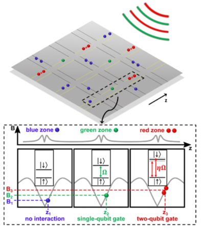
Figure 1: Voltages applied to local trap electrodes produce electric fields which hold the ions above the microchip. Changing the voltage changes the position of the ions. A local, position dependent magnetic field (magnetic field gradient) is applied to the ions. Changing the voltage moves the ions into a different magnetic field. A change in magnetic field changes the energy between the two qubit states. If the correct voltage is applied then the qubit energy splitting will be equal to the energy (frequency) of one of the globally applied RF and microwave fields which then implements a particular type of quantum logic gate. Moving the ion to a different magnetic field will then induce an interaction with a different RF and microwave field implementing a different type of quantum logic gate. A handful of radiation fields are therefore sufficient to implement quantum gates with arbitrarily many qubits. The number of radiation fields required for quantum gate implementation does not scale with the number of qubits therefore enabling practical large-scale quantum computers. [1]
In order to distinguish qubits from one another and strongly couple them to our global microwave radiation, we must use energy levels which are strongly sensitive to magnetic fields. This however means that they will be greatly affected by ambient magnetic field noise. Such states have coherence times on the order of 2 milliseconds [2]. Since two qubit gates take the same amount of time, it becomes impossible to run any sort of algorithm.
To circumvent this issue, we use dressed states. This involves applying microwave fields resonant with two of the energy level, which effectively protects the qubit against magnetic field noise. The qubit can then be manipulated with RF radiation (see figure 2).
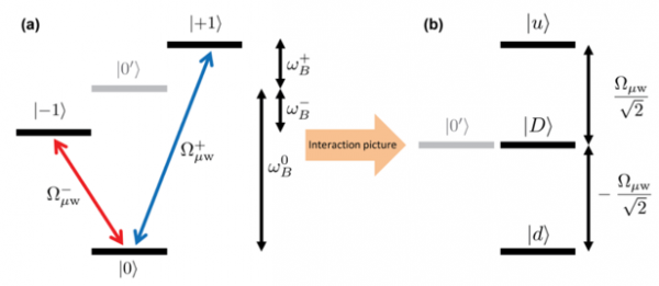
Figure 2: (a) Two microwave fields (the dressing fields) are resonant with magnetically sensitive states. (b) The dressing fields lead to new qubit basis state. Our new qubit is made up of the |0’> and |D> states which are less sensitive to noise. [3]
We have demonstrated that this dressed qubit can be used for quantum computing in reference [3]. We have also shown that this scheme leads to longer coherence times (see figure 3).
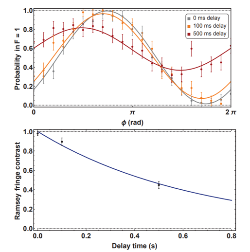
Figure 3: (Top) A Ramsey type experiment on our dressed state qubit. The amplitude of the oscillation indicates how well information is preserved. (Bottom) Decay of the amplitudes. A fit to this curve gives a coherence time of 0.65(5) seconds. [2]
[1] S. Weidt et al., PRL 117, 220501, 2017
[2] J. Randall, PhD, Imperial College of London, 2016
[3] J. Randall et al., PR A 91, 012322, 2015
Strong Spin-motion Coupling for High Fidelity Quantum Gates
All complex numerical calculations are built up using simple operations such as addition, subtraction and multiplication. To have confidence in the result of the calculation, it is vital to be able to say with certainty that there were no mistakes made in any part of these basic operations. The same is true for quantum computers, but in this case, these basic operations are governed by quantum mechanics and are called quantum logical gates. We are working to find ways of making sure these gates do not give a false answer, quantified by the success rate of at least 99.9%.
Although the problem can be stated in a simple way, the issue is that a single trapped ion is highly sensitive to perturbations by unwanted electromagnetic fields that could be coming from phones and other electronic equipment, vibration from pedestrian movement, and other changes to the environment that we cannot control. At the same time, to improve our quantum logic gates, we need to be able to deliver high power microwave and radio-frequency signals to the ion. Therefore, a large amount of our effort is balancing these requirements for ion isolation and exposure from the devices we develop. We believe we have found a way to achieve a happy compromise between these competing goals and work on demonstrating a record-breaking quantum logic gate.
Our group has developed a method of simplifying the way we manipulate the quantum state of the ion using a magnetic field gradient with microwave radiation. To improve how fast we can carry out quantum logic gates, both the strength of the gradient and the microwave radiation needs to increase. Our experiment includes several novel devices that address this issue. This includes a magnet setup, which generates strong magnetic field gradients and in-vacuum microwave emitting wires. We believe this is able to provide a 10 –fold improvement on the current state-of-the art technology developed in our group, pushing us well beyond the relevant fault-tolerant threshold.
One of the difficulties of working with surface ion traps is the potentially lower trapping depth, severely limiting experiment time. For large macroscopic traps, the ion lifetime can reach several weeks, whereas surface traps exhibit lifetime of several hours. One way of counteracting this, is to cool the trap, which minimizes collisions and heating of the ion. To this end, we have designed and assembled a cooling system which circulates cold helium through a heat exchanger, bringing the microchip structure down to -200° C.
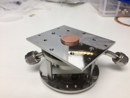
Heat exchanger for ion traps. Cold helium is circulated via the angled ports on the sides, while the protruding copper pedestal makes contact with the trap, exchanging heat.
By trapping a pair of Ytterbium ions in a system with all these enhancements, great effort is undertaken to carry out quantum logic operations.
Ion microchips with current carrying wires
The key challenge that is the engineering of a large-scale quantum entanglement hardware with microwaves comes in two steps:
The first one is the realisation of a high-fidelity and reliable quantum gate on a surface ion trap design. This can be achieved using permanent magnets to drive the spin-spin coupling between two ions.
To build a useful quantum computing machine we need to go further than realising a single entanglement operation between two ions. We need to create a large entangled network that can make use of an arbitrary large number of ions. Using surface ion traps, entanglement between many distant and remote ion qubits can be achieved by physically transporting the ions above the surface, therefore distributing the entanglement across the architecture. On an engineering side however, using permanent magnets in this configuration would mean that ions would experience significant magnetic fields as they are shuttled across the surface and in practice is to be avoided.
The second step is therefore to devise a magnetic field gradient scheme for qubit entanglement that is inherently compatible with our ion shuttling scheme. One solution to this problem is to implement switchable magnetic field gradients. The concept is simple: during entanglement operations, the magnetic field gradient is switched ‘on’, while during ion transport operation, the gradient is switched ‘off’.
In this scheme, the magnetic field gradient is generated using embedded current-carrying wires within the ion trap. There, the wires behave like small electromagnets which can be energised at the precise time when the magnetic field gradient is desired.
To tackle this overall challenge and demonstrate that we can perform entanglement across a large-scale architecture, we are currently developing surface ion traps integrating current carrying wire that could be operated with a switchable current of up to 13.6A and delivering magnetic field gradient of 150T/m .The current carrying wires are made of copper and are electrically insulated from the surrounding trap substrate, here silicon, using a thin layer of silicon nitride. See figure below.
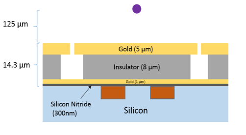
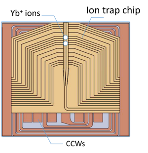
Figure 1: cutaway view (left) and top view (right) of a surface ion trap with integrated current carrying wires (orange colour) with an ion above the surface (purple/white dots).
We find that a useful ion height above the ion trap surface, to initially work with, to be of ~125mm ensuring practical laser alignment to the ion for Doppler cooling, state preparation and detection, while ensuring that the ion is not experiencing a too higher rate of motional heating, which could otherwise lead to significant infidelities during entanglement gates. Numerical models estimate that under such a large gradient, and given the ion-surface separation, gate fidelities can be expected much greater than our target threshold of 99% for fault-tolerant quantum computation.
In essence, current carrying wires provide a compact, scalable solution which can be implemented alongside complex surface ion trap design. This allows for the local generation of gradients on the chip, therefore avoiding coupling to other ions in the architecture and can be entirely disabled during shuttling. In addition, current carrying wires can be fabricated using standard microfabrication techniques with great accuracy. Being integrated within the chip, they also significantly reduce the experimental complication of precise planar chip to magnet alignment.
But every solution comes with its own set of challenges. To generate large magnetic field gradients, equally large currents need to be applied to the chip. In practice, these can heat up the chip significantly and requires mitigation. The generation of large switchable magnetic field gradient on a silicon chip therefore requires the construction of a cooling system. The heat conduction of silicon wafers is nearly as good as that of diamond at 70K. Indeed, operating the whole architecture around 70K leads to many advantages. From an ion trapping side, we get improved ultra-high vacuum capabilities as well as orders of magnitude reduction of motional heating, while on a thermal engineering side we reduce the thermal heat load due to reduced electrical resistivity of copper along with improved thermal management due to the increase thermal conductivity of silicon.
Within the laboratory, preliminary tests have already been conducted at ~86K using an ion trap designed for 100mm ion height, which was successfully operated under a current density of and would yield a gradient of 185T/m at the gate zone, see figure below. This has given us crucial insights in terms of microfabrication process repeatability, device optimisation and cryogenic thermal management.
We also recognise that, as the theory surrounding gate schemes progresses, motional heating may become less of a problem, therefore giving a strong advantage to setups capable of delivering extremely large magnetic field gradients without having to strike a trade-off with ion-surface proximity. For this, current carrying wires appear outstandingly promising as our models predict that gradients in excess of 1,000 T/m at an ion height of 40 µm can be generated using a current of 10A.
Fast and Accurate Ion Transport
In classical computers, information can be easily and rapidly communicated between different components using electrical wires. But how do we reliably communicate quantum-information, encoded in the energy states of the trapped ions, throughout a quantum computer? This issue can be very challenging, yet it is essential to solve if we wish to create a large-scale quantum computer.
Within a quantum computer, quantum algorithms are carried out by transporting ions or ion-chains to different zones within the computer, otherwise known as ‘shuttling’ where quantum gates are exectuted. In essence, just as coupled motional modes are the data-bus between two ions in a gate, ion transfer is the data-bus for quantum-information across different gates and zones within the computer. So how does this work? Because ions are charged particles, they can be ‘pushed’ and ‘pulled’ around using electric field. Therefore, if you can precisely control the electric field around the ion, you can precisely control its position and motion. This can be achieved by placing a train of DC electrodes along the path of the trap, as shown in Figure 1. A confining potential-well can be created by applying a potential to the electrodes such that the ion is attracted to the ‘centre’ electrodes but repelled by the ‘outer’ or ‘endcap’ electrodes, analogous to it being stuck at the bottom of a ‘bowl’. Then, one can move the ion by simply switching which electrodes attract the ion and which ones repel it, changing the shape and position of the confining-well (the bowl) and thus directing the ions along the RF-nil to different locations of the trap. These electrodes are fabricated into the surface traps and can be controlled by integrated voltage-supplies (DACs). This concept allows us to transport information around different zones of the trap and the computer by moving the ions around to the appropriate locations. Similarly, this technique allows operations such as ion-separation (splitting a bowl with multiple ions into two ‘subset’ bowls) and ion-recombination (merging two bowls each containing ions).
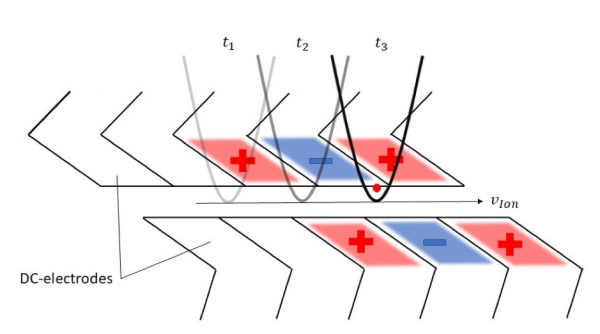
Figure 3: Trap DC-electrodes with confining potentials applied. These can be switched over time (t1, t2, t3) to move the ion along the trap, with velocity VIon.
However, ion-shuttling does not come without its challenges and is a subject of research within the Sussex group. Suppose you had a bowl full of water that you wish to carry to the next room, as you can imagine, any sudden movements will disturb the water and cause it to ‘slosh’ around. An equivalent effect occurs to the ion if the electric field holding it in place is switched too fast. In this circumstance, the effect of rapidly accelerating the ion causes it to heat up. Ion-heating is problematic for both gates and for ‘shuttling-fidelity’, which is the number of times an ion can be shuttled before it is lost.
One can imagine that if the bowl of water is carried very slowly, you can transport it with little to no disturbances in the water. This is also true for ions and is called ‘adiabatic shuttling’. It can be shown that if the potential-well is moved slower than the time-scale of the ions motion (the secular frequency), then no motional energy will be imparted to the ion and thus it shouldn’t experience heating. However, this comes with its own set of problems. Environmental interactions, such as ‘electronic noise’ and ‘surface patch potentials’, create small charge fluctuations on the trap surface and kick the ion causing it to heat up. A slow shuttle will mean longer exposure to these sources of heating and unless they’re severely mitigated, adiabatic shuttling can become challenging. Another important consideration is ‘run-time’, as slow shuttling will become costly when considering the overall processing time of the computer. One can try to increase the ions secular frequency, allowing a faster adiabatic shuttling speed, however this is very hard due to the limitations of how much potential can be applied to the trap.
Instead, research is focusing on a more sophisticated form of shuttling known as diabatic shuttling. One such example is called ‘Bang-Bang shuttling’. Here the ion is given a large kick from behind by rapidly increasing a potential. Very rapidly, when the ion has reached its destination, a front-kick is given that halts its motion and the stationary potential-well is restored. When timed exactly right, the added momentum from the initial kick is counteracted, and the ion is restored back into a ‘cool’ state. Other methods involve phasing, where the potential-well is moved at exactly the right time such that it matches the motion from the ion’s axial-secular frequency. Hence the well moves ‘with the ion’ as it oscillates inside the well. Many other interesting solutions to fast ion shuttling have been developed and continue to be developed and explored by our group.
Experimental realisation of quantum error correction
Just like bits stored in the memory of hard-drive of a classical computer, qubits in a quantum computer will accumulate errors over time, as a result of noise and hardware imperfections. Improving the accuracy of the fundamental operations and reducing noise can improve things, but eventually something is guaranteed to go wrong in an unpredictable way. The solution is fundamentally the same for quantum computers as for classical ones: keep redundant copies and implement an error-correcting code.
For simple classical bits you might encode “1” as “(1,1,1)” and “0” as “(0,0,0)”. Then if some electrical noise inside your memory causes one of the bits to change, and you end up reading out “(1,0,0)”, you can be pretty confident that the first 1 should be a 0, and so you can correct the error. Of course the assumption that errors are unlikely is important, with this scheme we can tolerate up to one error per 3-bit ‘codeword’, we could easily use 4- or 5-bit codewords instead but storing many copies is a lot of redundancy, and not very efficient. The family of “Hamming codes” are an optimally efficient extension of this idea, using just enough extra bits to identify where an error has occurred, and are widely used in RAM storage and wifi communication protocols.
Quantum errors are a bit more difficult to deal with for two reasons:
- A qubit can suffer the effects of noise in an analog fashion, unlike the digital nature of a classical bit. For instance, a spin direction might tilt just 2 degrees off the axis it should be aligned to.
- We can’t just look at every qubit in order to figure out what went wrong and how to correct the issue, because doing so would collapse the entangled quantum state of the quantum computer.
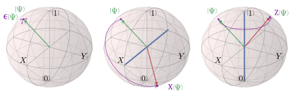
Small errors of unknown size and direction accumulate on the state of a qubit over time. Quantum error correction quantises the error. It forces the state to evolve either back to where it should be, or to the starting state’s opposite position, flipped about the X-axis (bit-flip) or the Z-axis (phase-flip).
Quantum error correction schemes deal with the first issue by projective measurement. By measuring a qubit that has experienced a small error, we collapse the quantum state into one of two exact possibilities: the original state with no error (with a high probability), or a completely flipped state (with low probability). If the error is quantised in this way, it can be treated in a digital sense, and the concept of codewords can be applied. It’s a little more complicated than the classical version though, and typically involves a nested set of Hamming-like codes because the quantised qubit errors consist come in two kinds: bit-flips, and phase-flips.
The second issue is dealt with by never examining one qubit on its own. We are careful to only ever extract partial information about a collection of qubits. We interact a small set of data qubits with a special-purpose “ancilla” qubit in such a way that the ancilla’s state reflects the number of errors present, but nothing about which specific qubit is incorrect. This way an entangled superposition can survive the error detection process, and by a clever arrangement of ancillas associated with certain sets of data qubits, it’s possible to puzzle out exactly where the quantum state has gone awry.
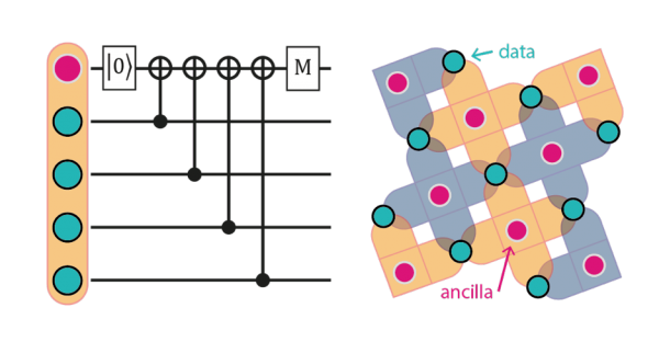
The surface code quantum error correction scheme uses special-purpose ancilla qubits to examine sets of data qubits in combination. This allows the extraction of information about errors without fully collapsing the entangled state for the quantum computer. The arrangement of sets to be examined form a square grid in 2 dimensions, making the scheme practical to implement with trapped ions on an array of microchips.
The specific scheme we are pursuing in the long-term to correct errors in a full-scale quantum computer is called “the surface code”. It is a very attractive scheme because the required sets of data qubits associated with each ancilla consist only of its next-door neighbours in a very practical square grid layout. It is ‘local’ in a way that many other quantum error correction schemes are not.
We are working toward a 2-dimensional grid of connected ion traps, which will natively support the surface code scheme in a scalable way, but the engineering challenges are significant. In the mean-time, we are road-testing the scheme in smaller ion-traps, which involves much more juggling of individual ion qubits in order to prepare the ancilla qubits for measurement. The other restriction in the short-term is that all the operations need to happen sequentially, but the immense power of the surface code to correct for quantum errors comes about when the many ancillas can be prepared and measured in parallel.
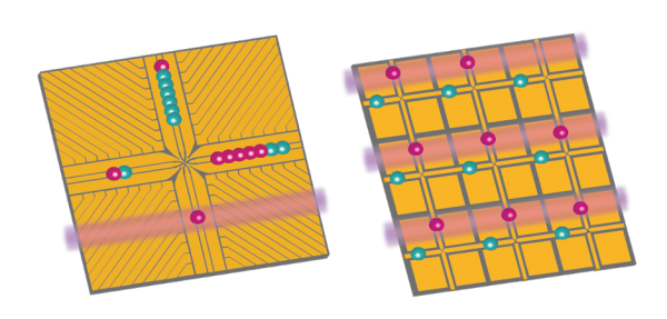
In the near term, the performance of the error correction process will be characterised in a single multi-zone ion trap, my rearranging up to 17 ion qubits and performing quantum gates sequentially. Eventually, simultaneous parallel operations will be possible on a larger array of ion traps.